“How is it possible that mathematics, a product of human thought independent of experience, adapts so admirably to the objects of reality.”
You can download the next files that are complementary for the explanation:
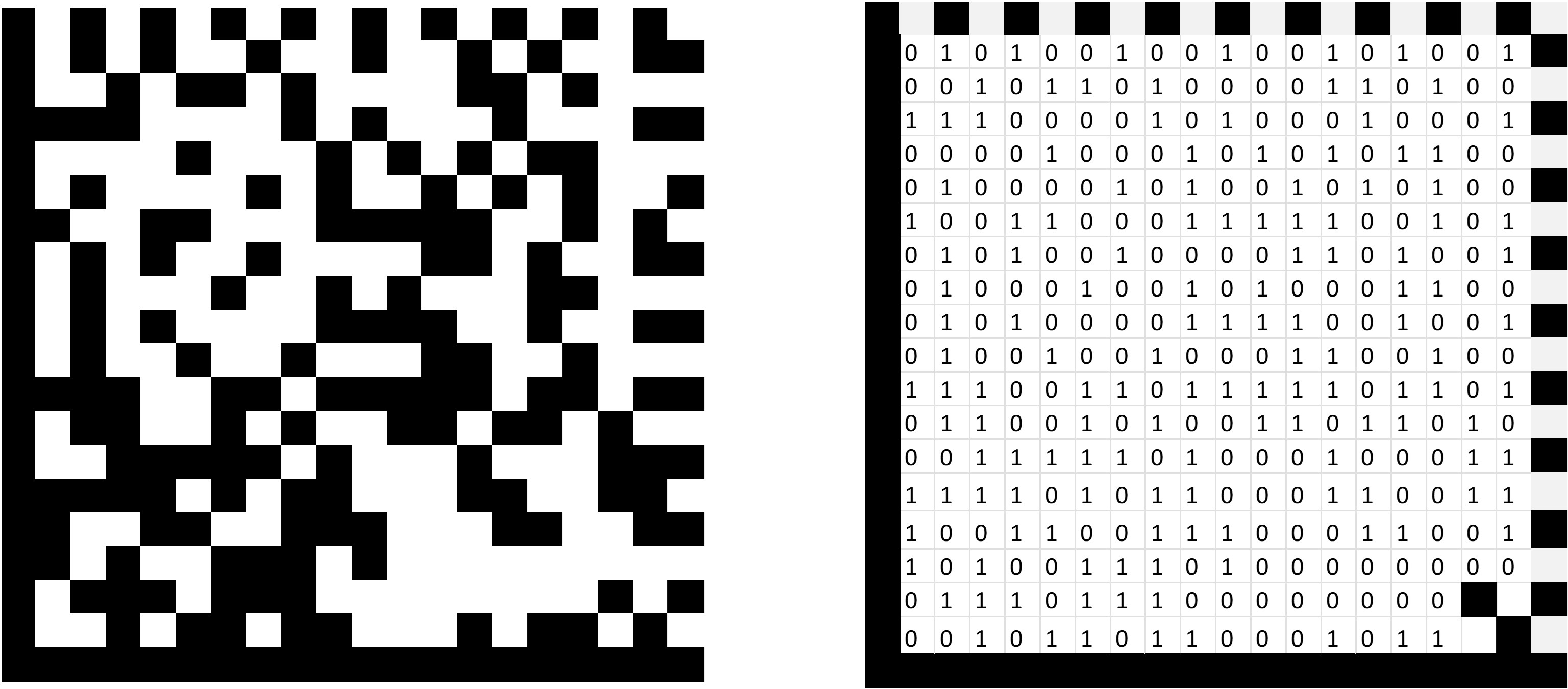
The common solution to generate a datamatrix code in a machining center is to buy a macro (SW has a very good but only work in sinumerik) or do the engraving after the machining process. But sometimes could be better to have a CNC program to engrave a code on the piece. A datamatrix code encodes a string of characters in a symbol. The symbol consists of a set of modules, each module represents a bit, a "full" module represents a 1, while an empty one is 0.
The symbol is limited by two lines that form an "L" that serve to align the symbol. On the opposite side it consists of two lines of full and empty modules placed alternately, this side determines the size of the module.
The string of characters to be encoded become "codewords," each codeword has an 8-bit length. The advantage of the datamatrix code is its redundancy or parity, as codewords are added that allow the character string to be recovered even though the symbol is incomplete or not properly scanned. This error correction process is achieved through the “Reed Solomon algorithm”
Reed Solomon's algorithm is based on “finite field algebra”. Understanding the algebra of fields is the most difficult part for a manufacturing engineer, but its implementation does not require such deep knowledge (although it would be desirable). The finite field algebra is not equal to the common algebra, which operates in an infinite field of numbers. The finite field algebra is based on a field with a limited number of elements. For example if we have a "field" of only two elements, 0 and 1, the sum of 0 and 1 is equal to 1, as in the algebra we all know. In the "normal" algebra the sum of 1+1=2, but it will be equal to 1 in the algebra of finite fields (for a two-element field). For example, suppose a field of 12 elements(1,2,3,4,5,6,7,8,9,10,11), as on a clock. If we add 12 to 12, the result would be 24 for the "normal" algebra, but it will be zero in the finite field. The explanation of the clock tells us that the result would be the residual of the operation, this can be expressed as a "modulo" operation (which can be performed in ms excel). The clock analogy can serve when we want to express a number on a finite element field. For example, the number 4 in a three-element field (0,1,2) would be equal to 1, which can also be expressed as 4 mod 1. The figure shows how a three-element clock (0,1,2) would express the number 4. The first three elements would complete a lap of three elements and only one element will be the remainder.
.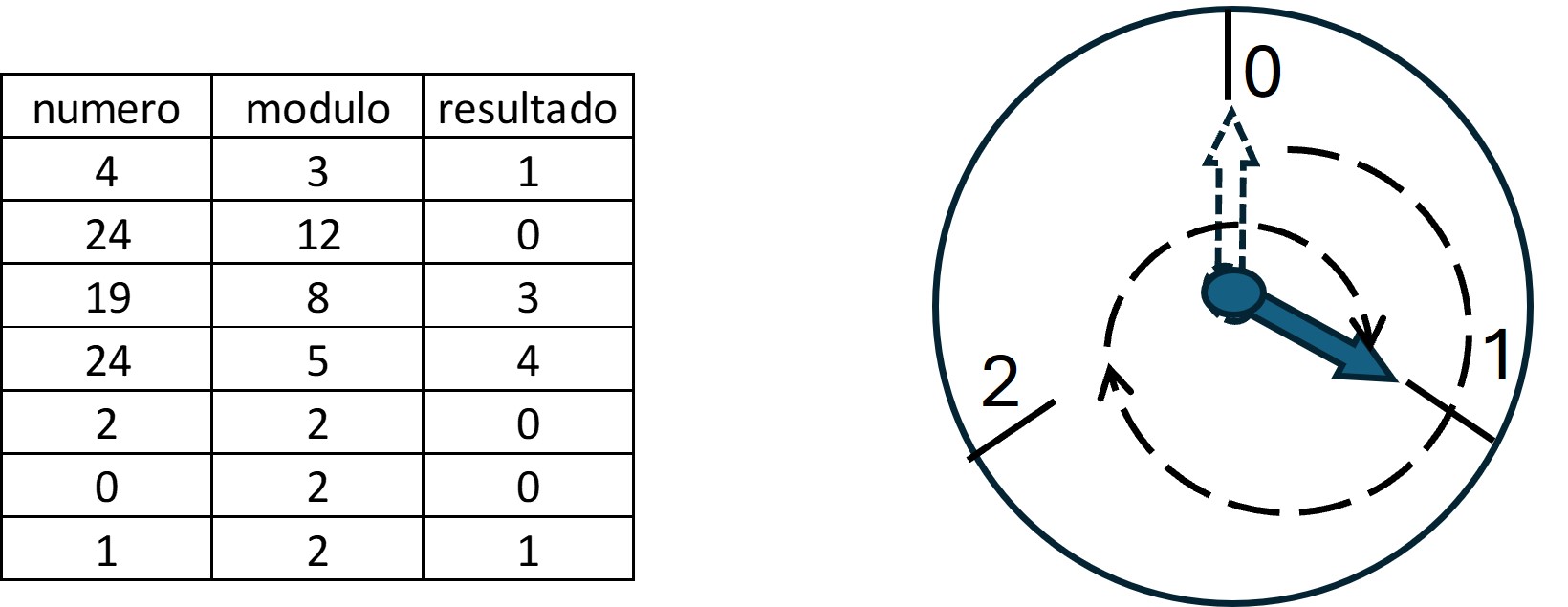
In general terms the idea behind Reed Solomon's algorithm is that according to Galois field theory, if we have a field of n elements we can reconstruct the entire field if we know the value of a lower-grade polynomial. The explanation is deeper but for our purposes it is enough. Thus, we can encode the character string as a polynomial of degree N which in turn is divided by a known polynomial. With the division remainder the error correction values can be constructed. All these operations will take place within a field of 256-element (0,1,...255).
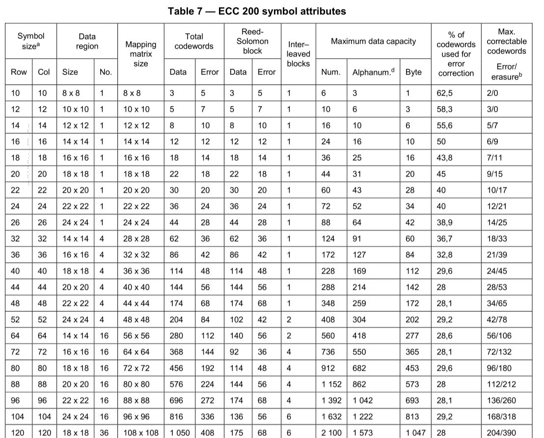
The number of data codewords that can be stored in a symbol is determined by the number of rows and columns. It is important to clarify that the number of "codewords" is not necessarily equal to the number of characters we want to encode, since there are ways in which more than one character can be grouped in a codeword
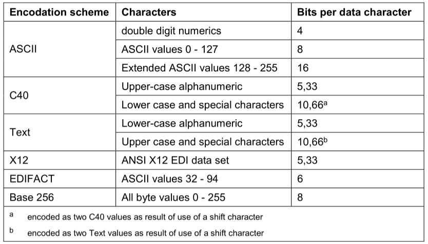
There are various encodation schemes, the ASCII scheme is used by default. Others have certain advantages such as being able to encode more characters into a single codeword, although they are more limited in the characters they can encode. The attached table shows how the ASCII encodation may require up to 16 bits to encode a character, but C40 mode only requires 5 in some cases, with the disadvantage that C40 mode is limited to fewer characters. Each mode has different rules for encoding characters.
The steps to encode a string of characters would the following:
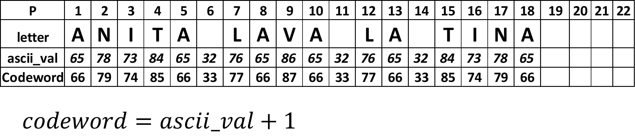
The phrase "ANITA LAVA LA TINA" will be encoded in ASCII scheme. The number of characters is 18, so we will choose an 18-row symbol, which can store up to 22 data codewords and 18 error correction codewords. Figure 5 shows the location of each bit of the codewords.
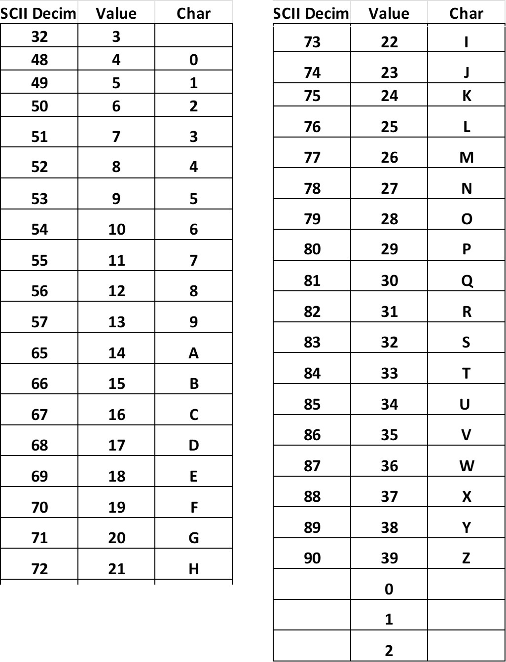
The encoding is always based on the decimal value of the character according to ASCII table (Figure 6 and 7). and follows the next rules.

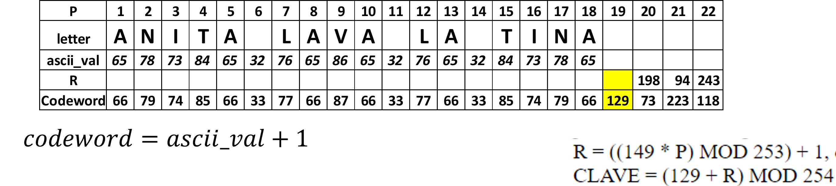
A 18-row symbol can store up to 22 data codewords, but the character string has only 18. When there are extra codewords, they will have to be filled using the following rules:
Figure 8 shows the complete codewords for the data, due the the string is only text (no numbers) each character corresponds to a codeword, in addition 4 codewords for empty spaces are added.
The codewords found will be used as the data polynomial coefficients in Reed Solomon's algorithm. In a very general way the objective is to build a final polynomial c(x). According to the formula of Figure 9.
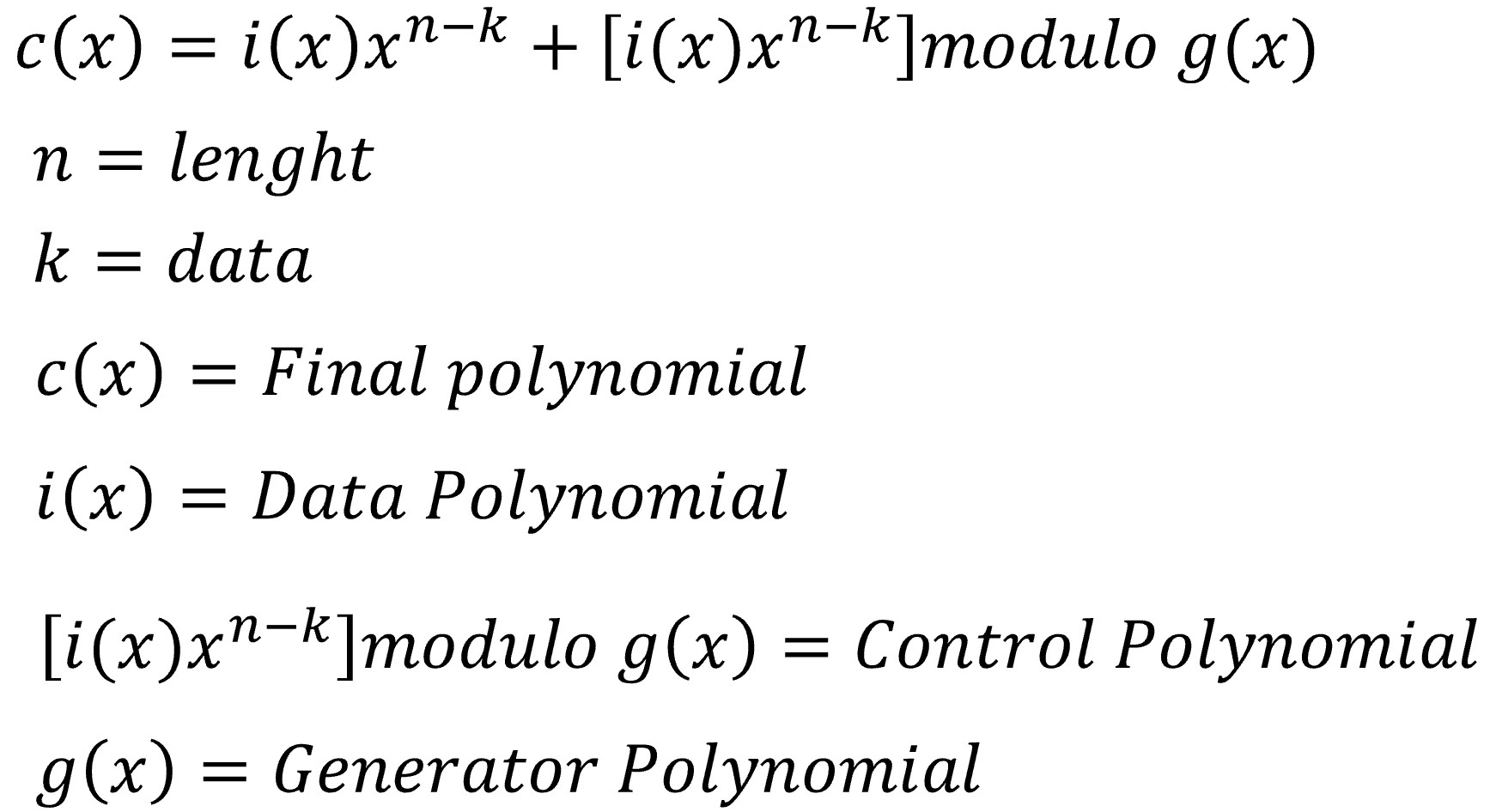
The degree of the data polynomial is established according to the number of data codewords k, in this case the number of codewords is k=22, the degree is k-1=21 since the value of the powers begins at zero (0,1,...21). This polynomial multiplies by x IS raised to n-k. The purpose of this operation is to leave room for control polynomials.
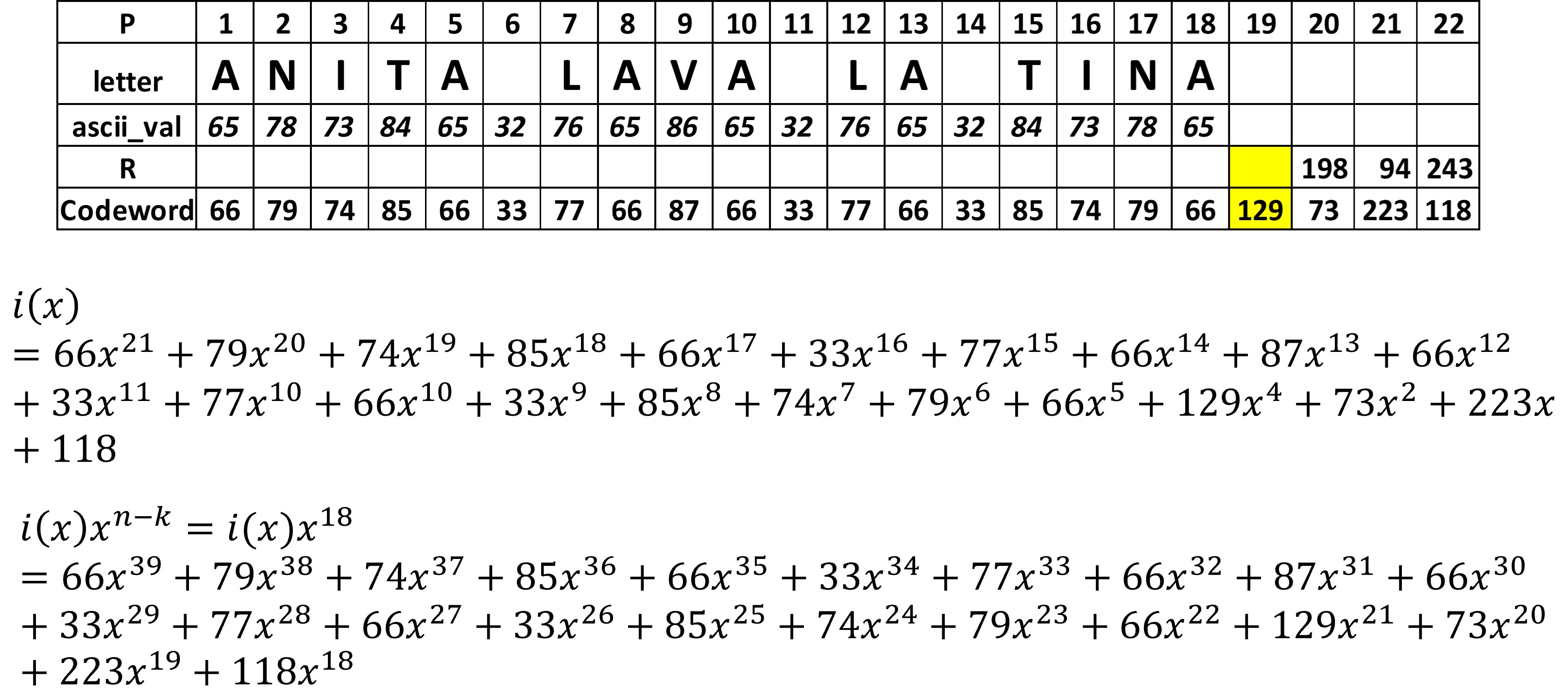
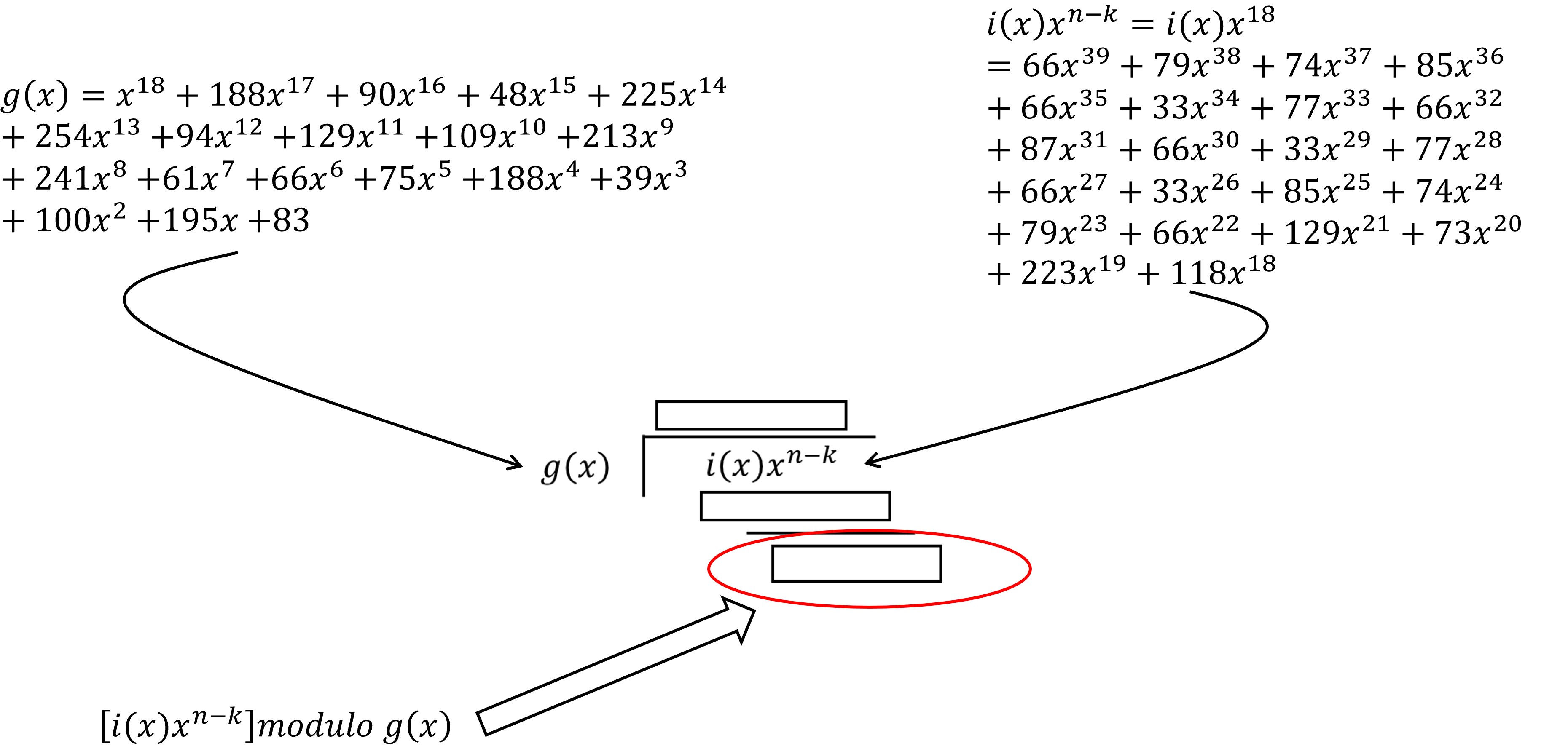
Figure 10 shows the first part that composes the final polynomial c(x) The control polynomial is a modulo operation, that is, the remainder of the division of the polynomial i(x)x^(n-k) between the polynomial generator g(x). The polynomial g(x) can be calculated using algorithm provided in the standard IEC 16022, however the standard also provides them completely developed according to the number of data correction codewords. For our example with 18 error correction codewords, the polynomial is shown in Figure 11. Figure 12 shows a visualization of the module operation, which shows that the result would be the remainder of the division of the polynomial data between the polynomial generator.

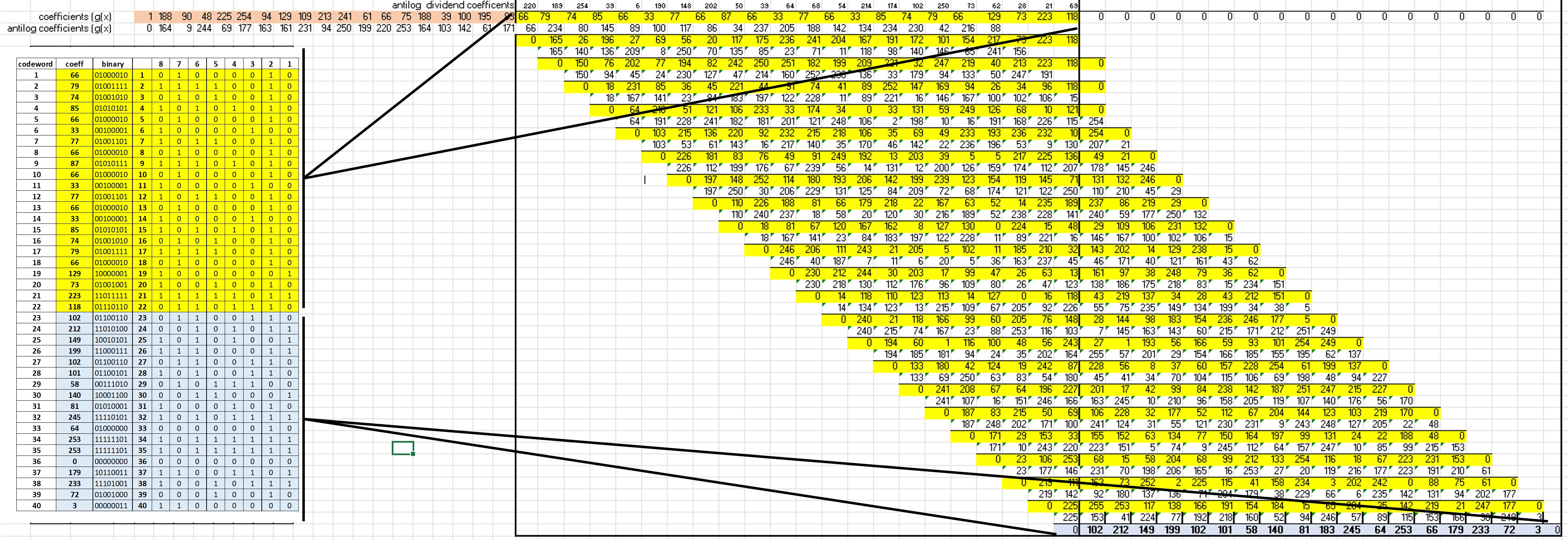
The polynomial division must be carried out in the finite field of 256. To make it easier, special logarith tables are used for that field.
The process consists of obtain the anti-logarithms (in the finite field 256) of the dividend and divisor coefficients. The process is repetitive for each coefficient of the dividend. At each stage the antilogarithm of the dividend coefficient is added to the antilogarithm of each divisor coefficient, that sum is modulo 255, and for that result the logarithm is obtained. When the sequence is completed for each divisor coefficient, an XOR operation is performed to obtain the result and the process is repeated.
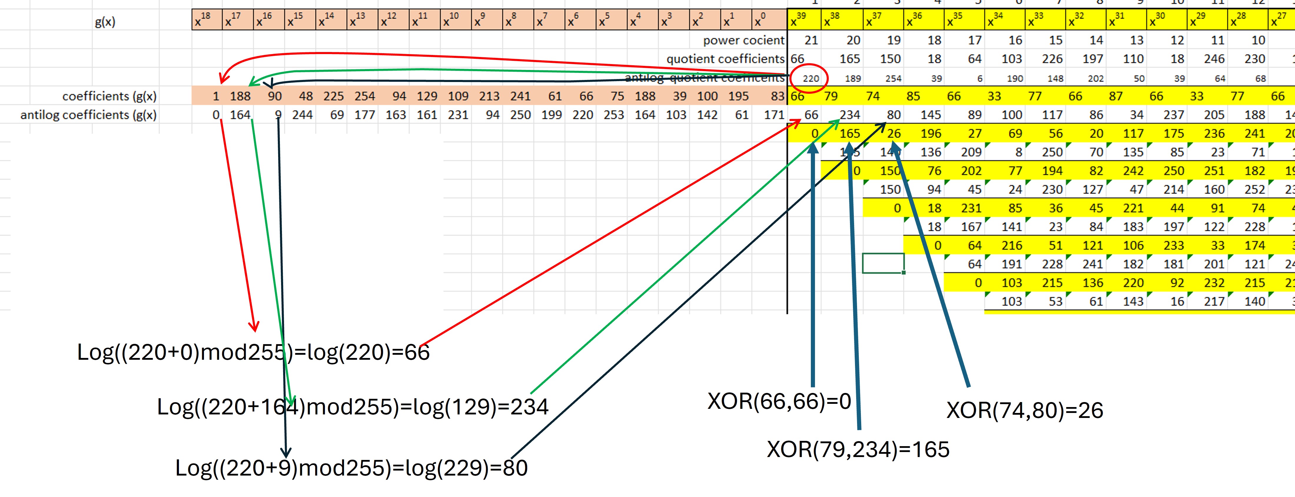
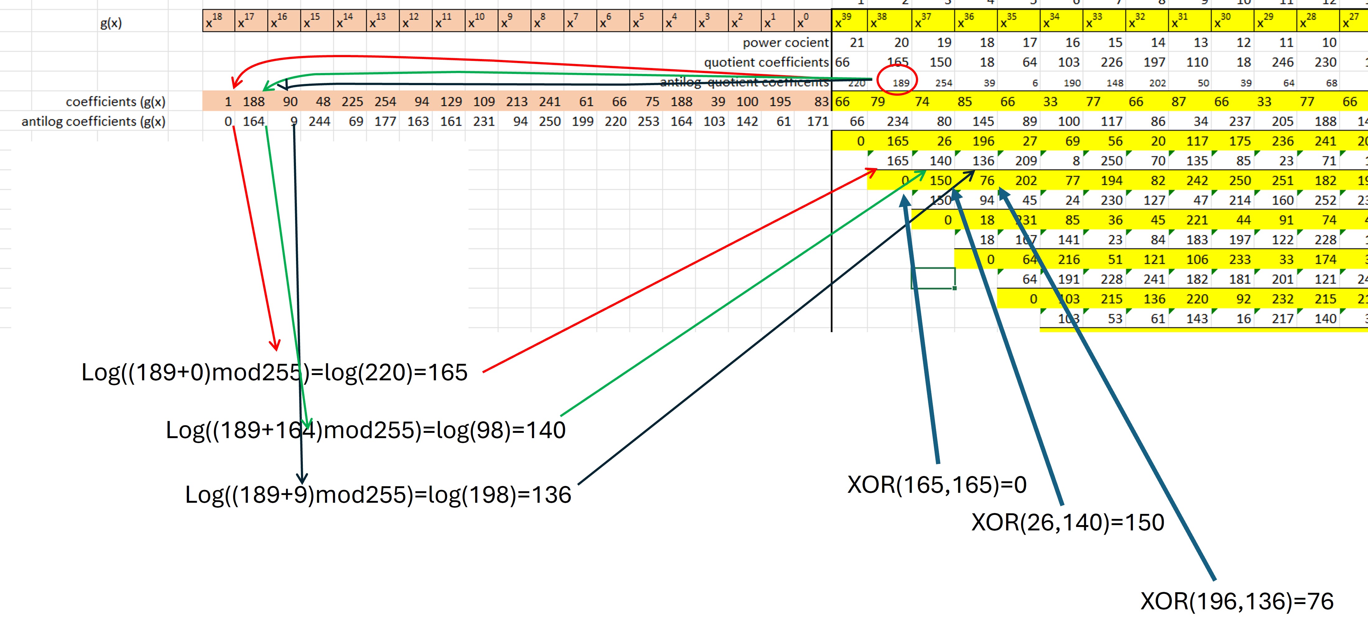
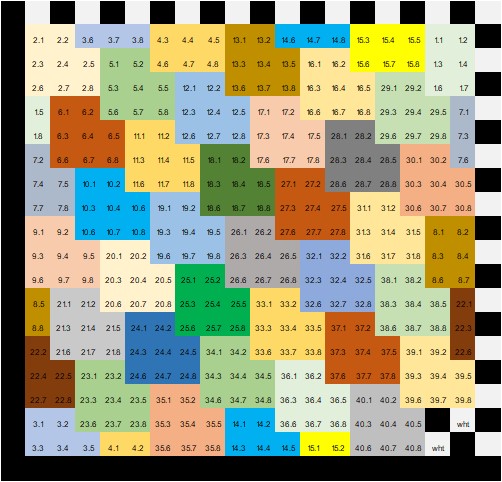
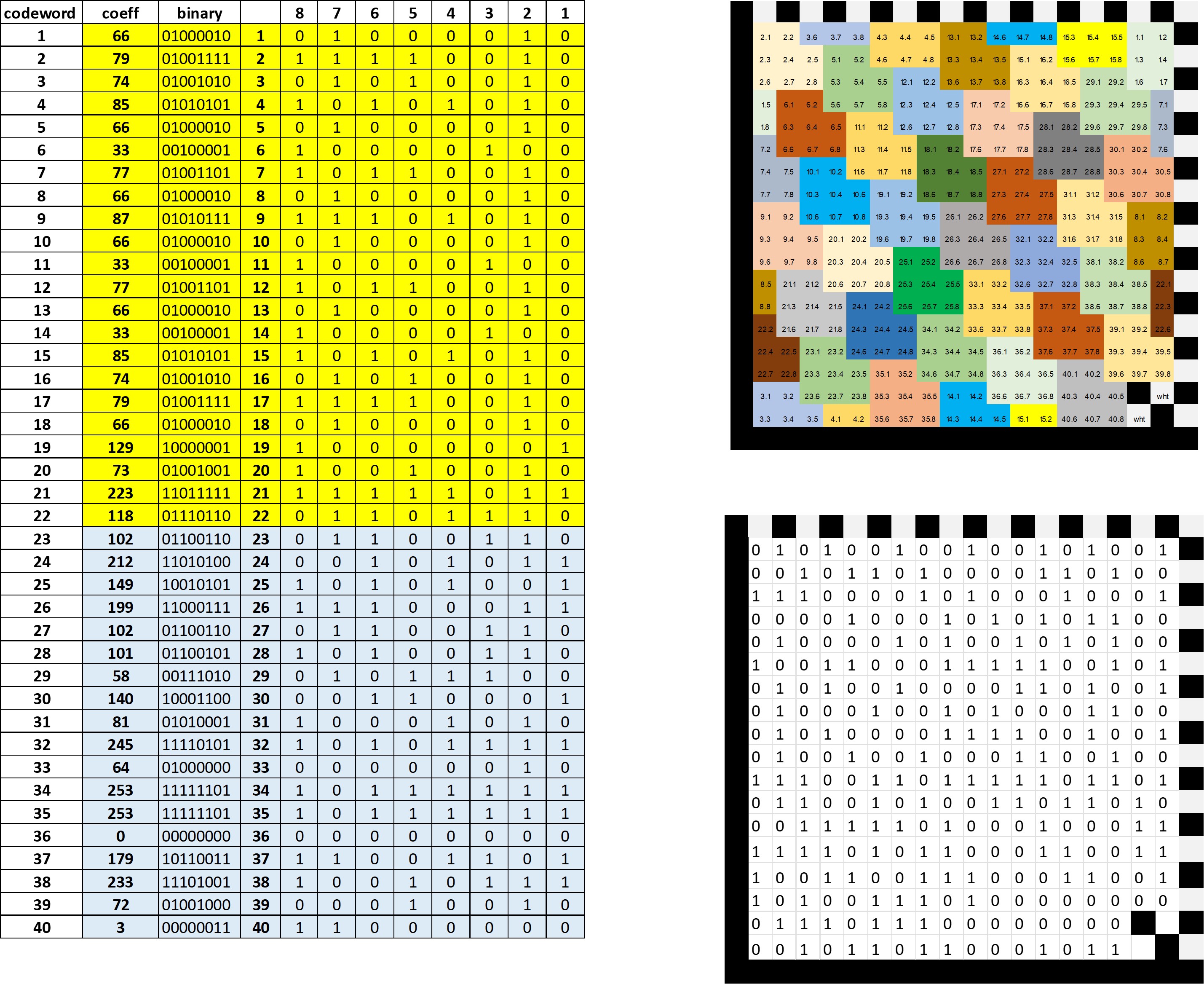
When completing operations for all dividend coefficients, a remainder will be obtained, which is the modulo. the remainder values are the coefficients of the polynomial control (Figure 9). The coefficients of the polynomial data are shown in yellow in Figure 16, and in blue the coefficients of the polynomial control.
Each codeword obtained from the previous process should be expressed in the form of 8 bits. Each of the individual bit values are accommodated according to the symbol mapping of Figure 5. At the end the values of 1 are expressed as a full module and zeros as an empty module, the process is now complete (Figure 17)

We will encode a serial number consisting of 13 alphanumeric characters ("02AD23MH06001"), formed only by capitals and numbers. Due to it is a machining operation we are interested in using the fewest characters, so instead of ASCII scheme we will use C40 mode. This scheme allows to group 3 characters into two codewords, allowing to save space and time.
Regarding the symbol, the most suitable for our purposes is one of 16 X 16, which is capable of storing 12 data codewords and 12 error correction.
In C40 scheme each character has a decimal value, each 3 consecutive characters (C1, C2, C3) are encoded with the formula (1600*C1)+(40*C2)+C3+1.
This formula generates a value from 1 to 64000
Two codewords are obtained
As the default schemes ASCII, we should indicate the change to C40 scheme using the codeword 230 (latch code) before the rest of data codewords. If go back to ASCII scheme is needed, codeword 254 is added and the coding in ASCII scheme is used (equal to the decimal value plus one).
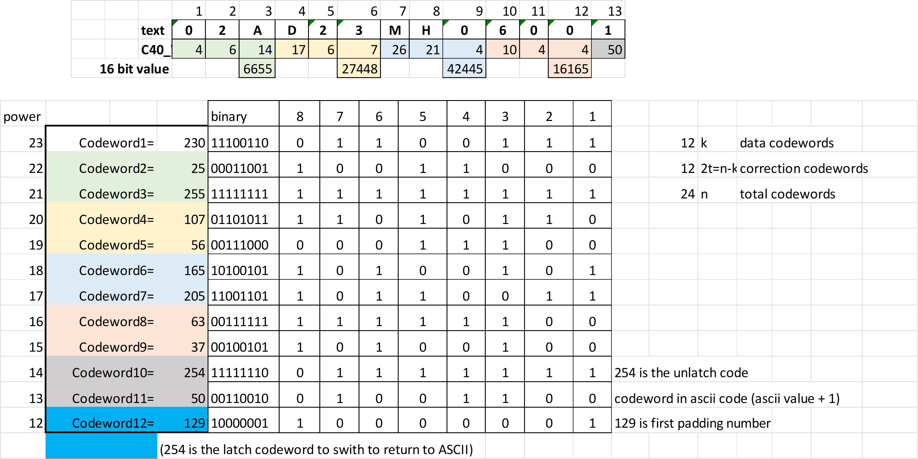
Figure 18 shows the calculation of the 16-bit value for the first three characters. Each character has a value according to the value of the table for the code C40.
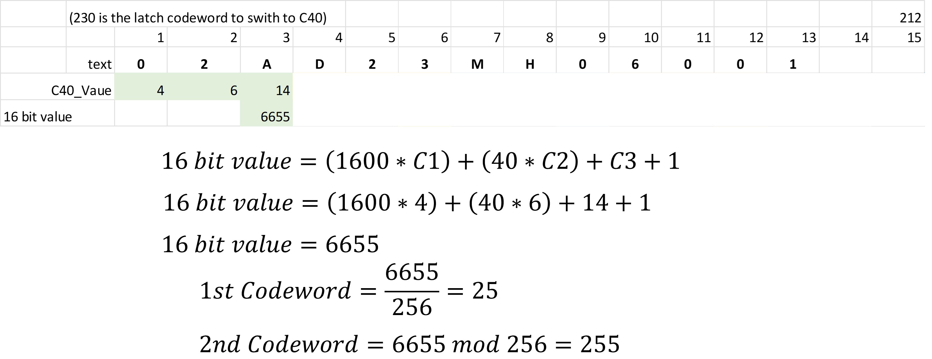
When calculating the 16-bit value we see that there are only enough characters to complete 4 16-bit values. From each of these values two codewords are obtained, that is, we have 8 codewords. The first codeword to the data should be the 230 to indicate that we are changing to C40 mode, then put the data codewords, which are 8 in this case, so we have 9 codewords of 12 available. We see that we have to encode a one character, which for simplicity is encoded in ASCII, so the tenth codeword will be the value 254 to return to that scheme. The eleventh codeword would be the value of the character in ASCII scheme (decimal value plus 1), and the twelfth codeword would be a padding value (129).
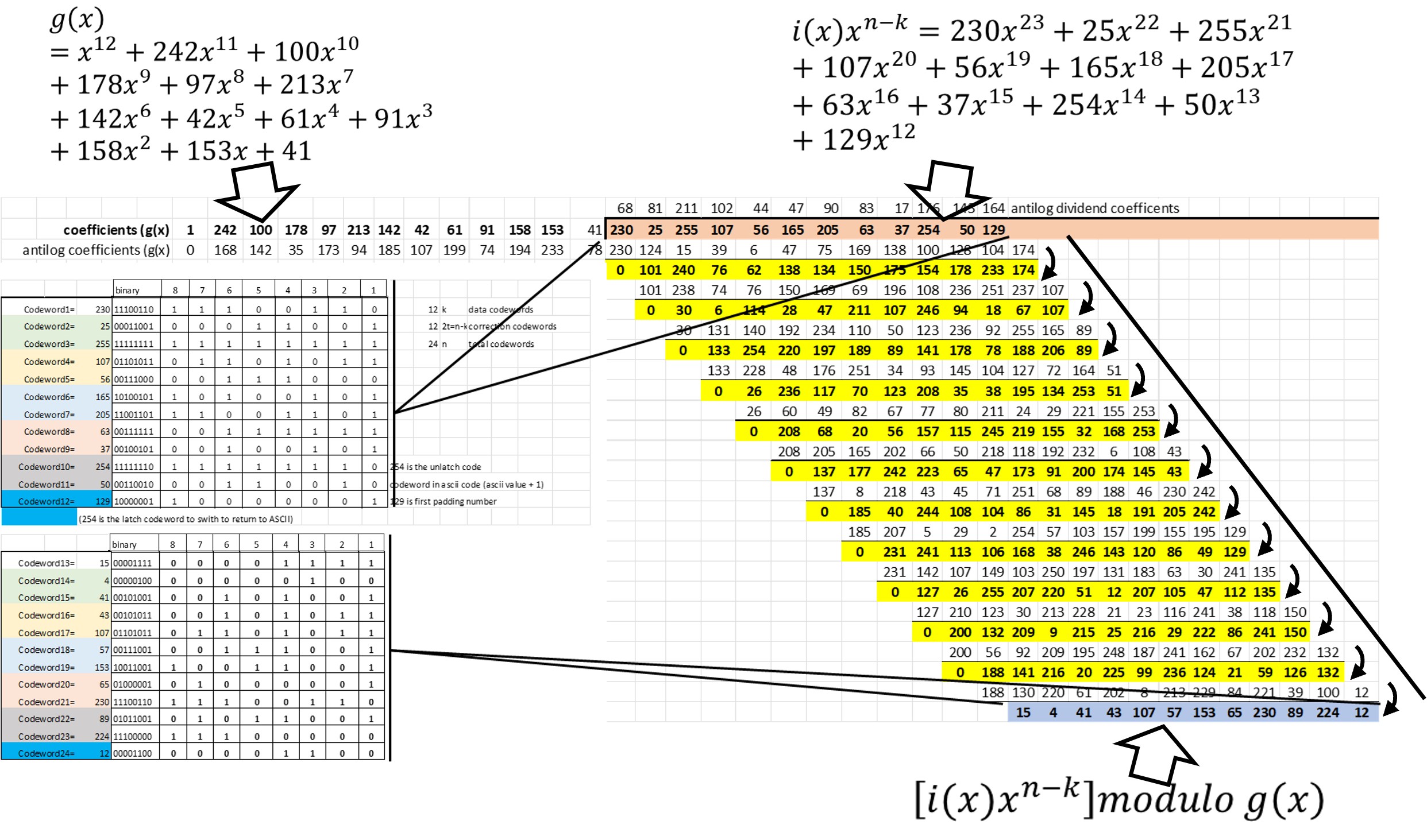
The error correction codewords would also be 12 and are obtained as shown before: from the expanded polynomial division using as dividend coefficients the data codewords previously obtained. The values of the divisor polynomial g(x) are obtained from the IEC standard.
The division process must be carried out in a recursive way until the remainder is obtained. Each stage has to use the antilogarithms (base 256) performing an XOR operation.
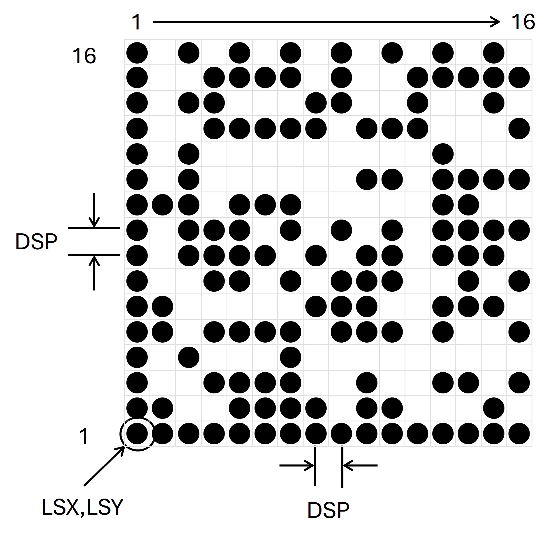
To create a program in CNC it is only necessary to convert each module of the symbol into a coordinate and to program a marking if the module is 1 and omit it if it is 0..
The edges of the symbol have values already defined, so their programming is simple. By dividing the entire symbol into columns we only require to determine the individual value of each point. We will identify the position of the lower left corner by the coordinates (LSX, LSY), the value of the DSP variable will be the space between points.
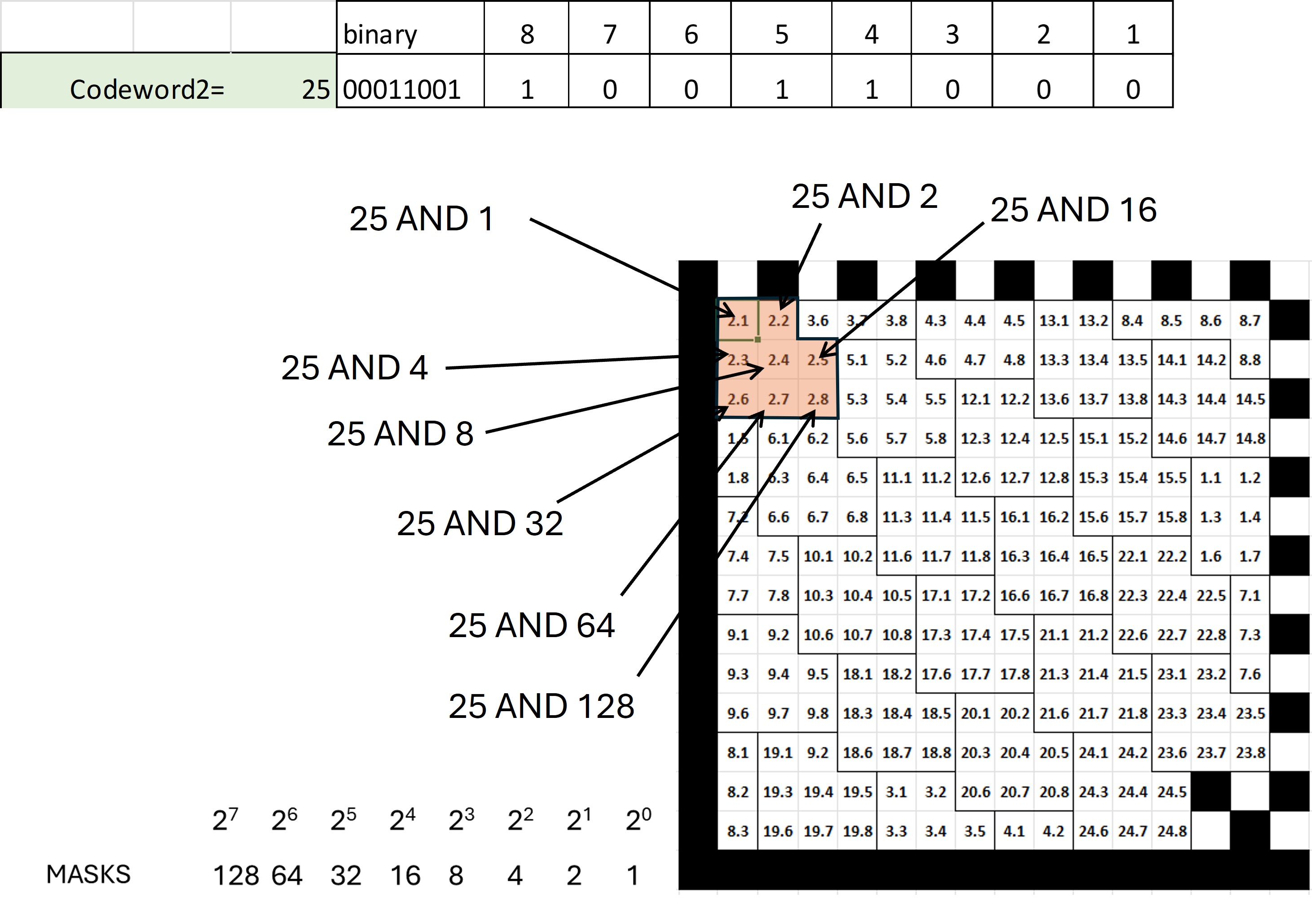
Each codeword consists of 8 bits and each bit has a predefined location in symbol. Figure 21 shows how the value of codeword 2 has a value of 25 that is 00011001.
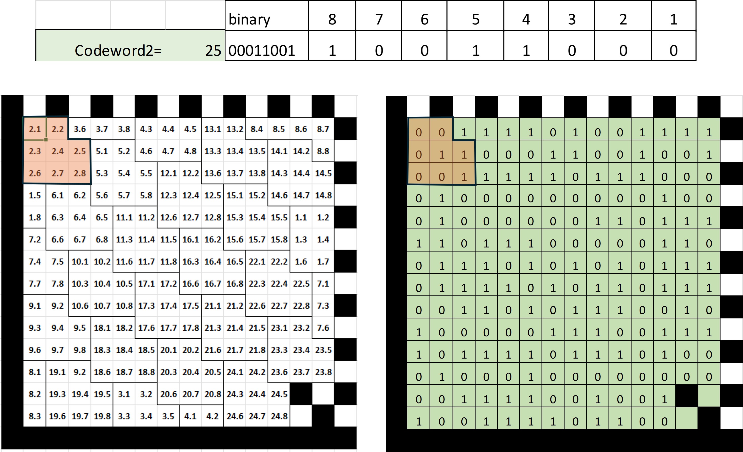
When the marking is programmed, the value of each bit should be isolated according to its position in the symbol. The way to achieve this is through a "mask" with an AND operation with a binary value that only has the value "1" in the same position of the bit we want to isolate.
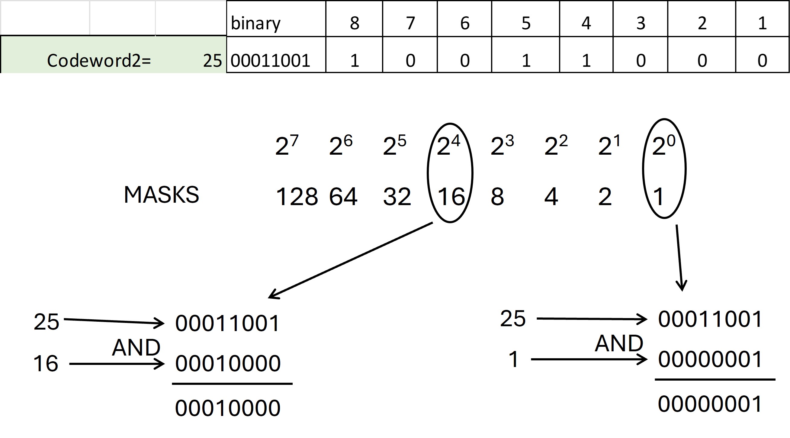
Figure 25 shows how AND operations would be performed for each bit of codeword 2 whose value is 25 (00011001).
The macro structure is as follows:
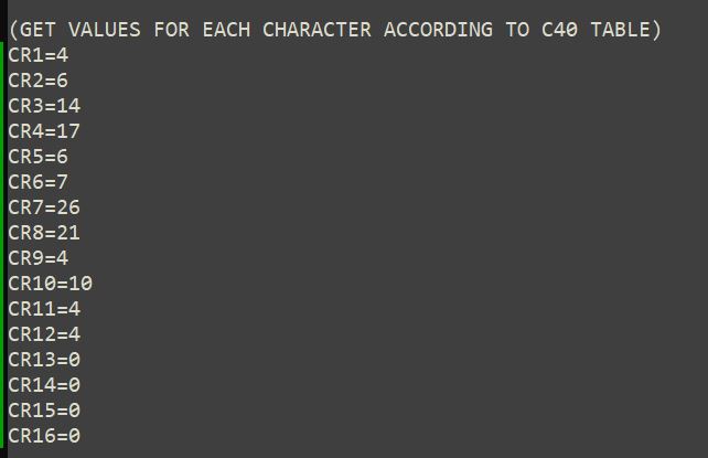
Figure 25 shows how the values are declared in the macro for the characters of our example according to Table C40, in this case they are being declared directly.
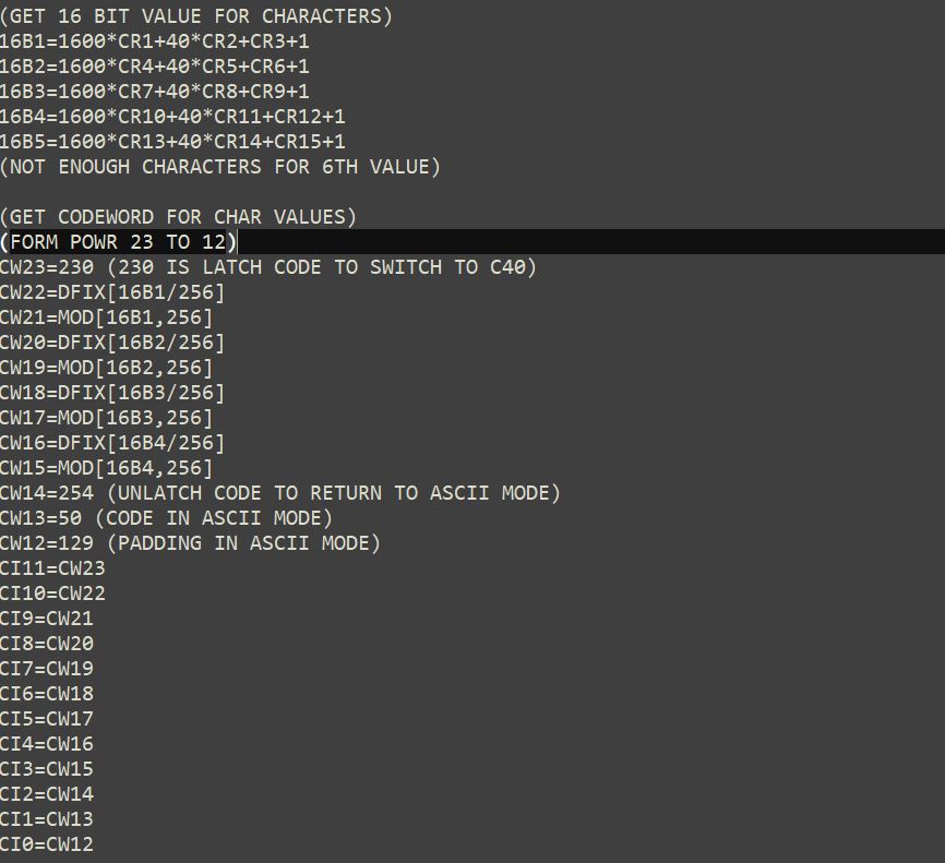
The 16-bit values and the codewords are calculated right away. The values of the dividend coefficients are stored in "temporary" variables CI. In this case the symbol can accumulate 12 data codewords and 12 error correction codewords. The data codewords (12) are stored in the variables CW23 to CW12 (the number corresponds to the power of the variable). The variables CW0 to CW11 (the error correction codewords) will be obtained from the polynomial division.
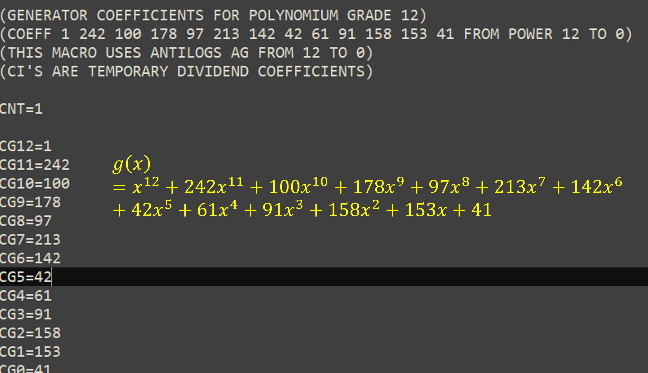
The value of the polynomial for generating the error codes g(x) has to be declared directly (Figure 28)
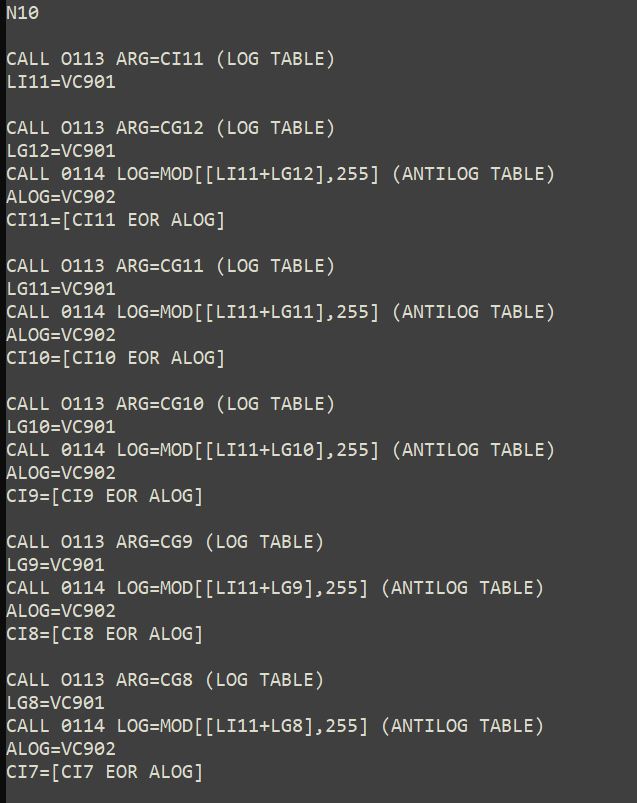
The the division operation is done iteratively using the logarithms and antilogarithms tables. The operation requires XOR operation.
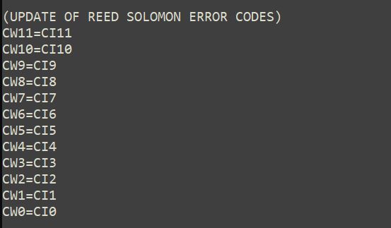
The values resulting from the division remainder update the error correction variables (Figure 29)
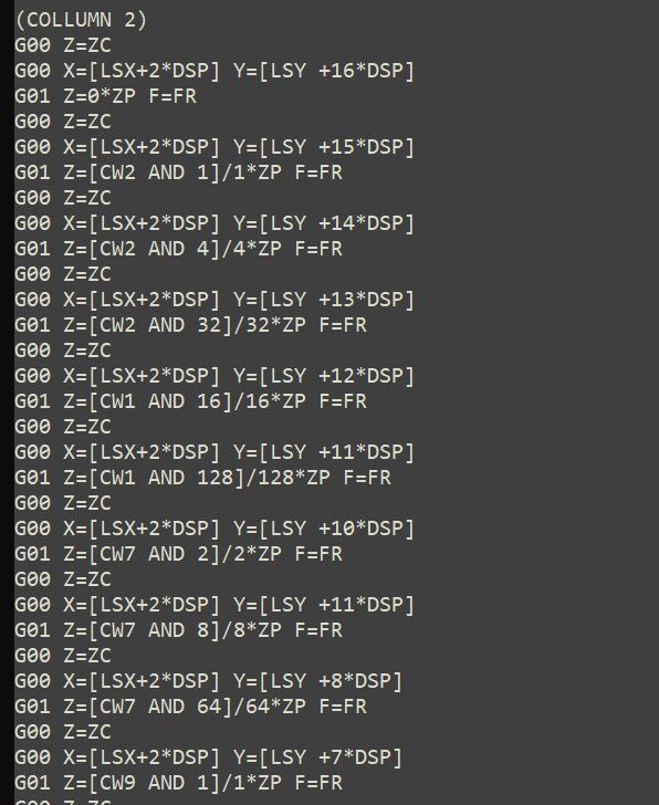
Finally, the marking is made. The code is arranged in columns so that an AND operation determines whether the corresponding bit is 1 or 0..
You can make the macro more sophisticated in a way that automatically calculates the size of the symbol and the operations for the marking, but the purpose was to keep it as simple as possible.